
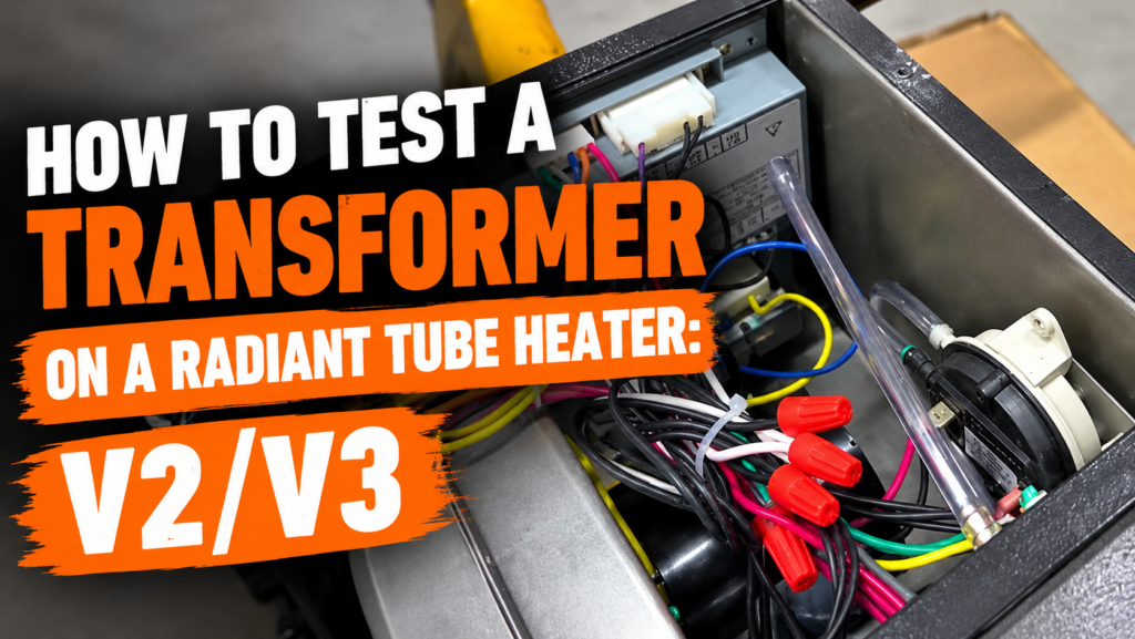
How to Test a Transformer on a Radiant Tube Heater: V2/V3
Introduction
Detroit Radiant Products newest burner box design is referred to as the V3 Burner. This includes a service access door which can be opened while the unit is running for easier serviceability. This blog and video go over how to test a Transformer on these units.
Testing the transformer on a Detroit Radiant Products radiant tube heater comes down to two checks: verify the incoming 120 volts, then check for 24 volts coming out. A multimeter lets you confirm both before moving on to replacement.
The testing approach is the same for V2 and V3 burner boxes. The difference is how you access the transformer and remove its mounting screws.
Safety first: Gas-fired equipment and electrical components should only be serviced by qualified personnel following the manufacturer’s instructions and local codes. Voltage testing involves energized components. Disconnect power before removing wiring or replacing the transformer, and follow applicable electrical safety procedures. The OSHA electrical safety guidance provides additional context on electrical hazards.
Access the Transformer
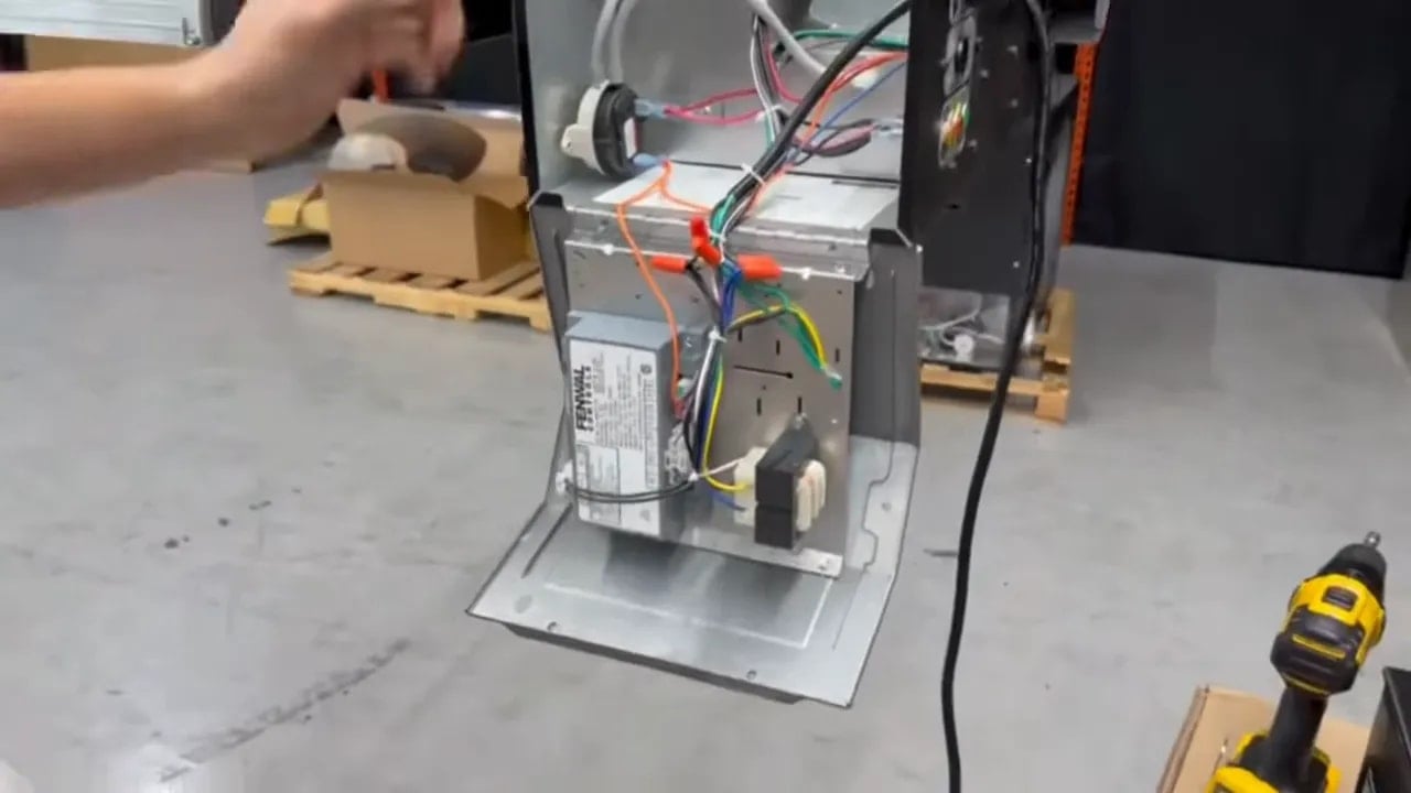
V3: Open the service panel
The V3 burner box includes a service access door designed to make components easier to reach during service. To access the transformer:
- Remove the four thumb screws securing the lid.
- Lift off the lid.
- Open the service panel to expose the transformer and wiring.
The V3 design allows the service access door to be opened while the unit is running. That serviceability feature does not eliminate the hazards of working around energized equipment.
V2: Remove the top cover
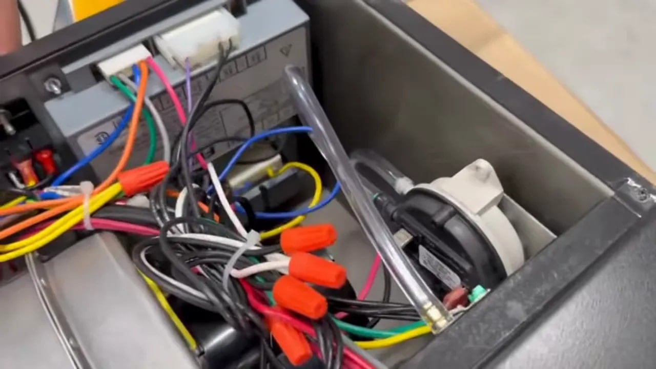
On the V2 burner box, access is through the top. Remove the six quarter-inch-head screws securing the cover, then lift the cover away to reach the internal wiring and transformer connections.
Use the manufacturer’s wiring diagram for the specific heater to identify the correct test points. Do not rely on wire color alone.
Check the Incoming 120 Volts
You will need a multimeter to measure voltage on both sides of the transformer. Start with the incoming supply so you know the transformer has power available.
- Locate the incoming power-cord connections.
- In the demonstrated check, place one meter probe on the incoming hot connection and the other on ground.
- Check for approximately 120 volts.
A 120-volt reading confirms the expected incoming voltage at those test points. Follow the manufacturer’s instructions for the required supply checks and probe locations on your particular unit.
Verify input before judging output. If the expected incoming voltage is not present, a missing output reading by itself does not establish that the transformer is bad.
Check the 24-Volt Output
Once the incoming supply is verified, measure the transformer’s output. Follow the blue output lead and measure between that connection and the corresponding common connection.
The expected reading is approximately 24 volts. In this check, 120 volts coming in and 24 volts coming out indicate that the transformer is providing the expected output.
- Incoming supply: approximately 120 volts.
- Transformer output: approximately 24 volts between the blue lead and common.
If the incoming voltage is correct but the expected output is absent, continue diagnosis according to the manufacturer’s service instructions before replacing the transformer.
Replace the Transformer: V3 vs. V2
If diagnosis establishes that replacement is needed, disconnect power before touching the wiring or mounting hardware. The following is the basic removal and replacement sequence, not a substitute for the model-specific service instructions.
V3 replacement
- Disconnect power to the heater.
- Remove the two transformer mounting screws.
- Transfer the hot, common, and ground connections to the replacement as specified by the manufacturer.
- Install and secure the replacement transformer, ensuring all required connections are restored correctly.
The open service panel provides access to the transformer and its connections, making the V3 replacement process straightforward.
V2 replacement
With the V2 top cover removed, the transformer wiring is accessible inside the burner box, but the mounting screws are reached from outside.
- Disconnect power to the heater.
- Remove the six quarter-inch-head screws and top cover if they have not already been removed.
- Disconnect the existing transformer wiring at the bottom connections.
- Use a flathead screwdriver from outside the burner box to remove the two transformer mounting screws.
- Install the replacement transformer and reconnect the wiring according to the manufacturer’s instructions.
Keep the Diagnosis Simple
The key is to check both sides of the transformer: 120 volts in, 24 volts out. The V2 and V3 use the same basic voltage checks, while their cover access and transformer mounting arrangements differ.
Confirm the supply, check the output, and disconnect power before replacement. For radiant heating equipment, replacement parts, or technical support, contact Great Lakes Radiant at (888) 501-0252.
Need Help Troubleshooting a Radiant Heater Transformer?
If you’re troubleshooting a Detroit Radiant Products radiant tube heater with a suspected transformer problem, Great Lakes Radiant can help. We provide radiant heating equipment, replacement parts, and technical support for contractors and heating professionals.
📞 (888) 501-0252
📧 sales@glradiant.com
🌐 www.glradiant.com